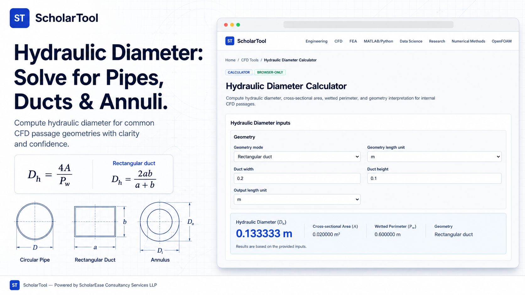
Hydraulic Diameter Calculator: Pipes, Ducts & Annuli Tool
When I am preparing a Computational Fluid Dynamics (CFD) simulation for an industrial ventilation system or a complex cooling jacket, I rarely have the luxury of working with simple circular pipes. Most real-world internal flow passages are rectangular ducts, concentric annuli, or even irregular custom sections. The challenge arises when I need to apply standard correlations like the Reynolds number or the Darcy-Weisbach friction factor which were originally developed for circular geometries. To bridge this gap, I need to find the “equivalent” length scale that represents the balance between inertial and viscous forces.
What I find indispensable for this task is the Hydraulic Diameter Calculator from ScholarTool. It is a deterministic, browser-local utility designed to resolve diverse geometries into a single characteristic length ($D_h$). Whether you are solving for a high-aspect-ratio duct or a narrow annulus, this tool ensures your simulation’s length scales are grounded in established fluid mechanics principles before you set your inlet boundary conditions.
What is Hydraulic Diameter and Why Use It?
In technical terms, the hydraulic diameter is defined as $D_h = 4A / P_w$, where $A$ is the cross-sectional area and $P_w$ is the wetted perimeter. As noted in the Elements of Computational Fluid Dynamics, many dimensionless ratios like the Reynolds number rely on a characteristic length ($L$) to categorize flow behavior. For a full circular pipe, the hydraulic diameter is identical to the geometric diameter.
However, for non-circular passages, $D_h$ provides an “effective” diameter. Why is this necessary? Because viscous resistance occurs at the walls (the perimeter), while the mass of the fluid moves through the area. By using the ratio of four times the area to the wetted perimeter, we can use circular-pipe correlations to predict pressure drops and flow regimes in shapes that aren’t circular.
A Comparative Perspective: Circular vs. Non-Circular
From a comparative perspective, treating a square duct or an annulus as a simple pipe is a common mistake that can lead to significant errors in pressure drop prediction. For instance, in a concentric annulus, the wetted perimeter includes both the inner and outer walls. If you were to use only the outer diameter, you would underestimate the viscous drag and produce non-physical results.
The ScholarTool interface handles these distinctions naturally. While a circular pipe input is straightforward ($D_h = D$), the tool’s specialized modes for rectangular and annular geometries account for the specific perimeter-to-area relationships that define those shapes. This ensures that you aren’t just guessing an “equivalent” size but are using the mathematically resolved characteristic length required for accurate CFD.
Inputs You Can Use
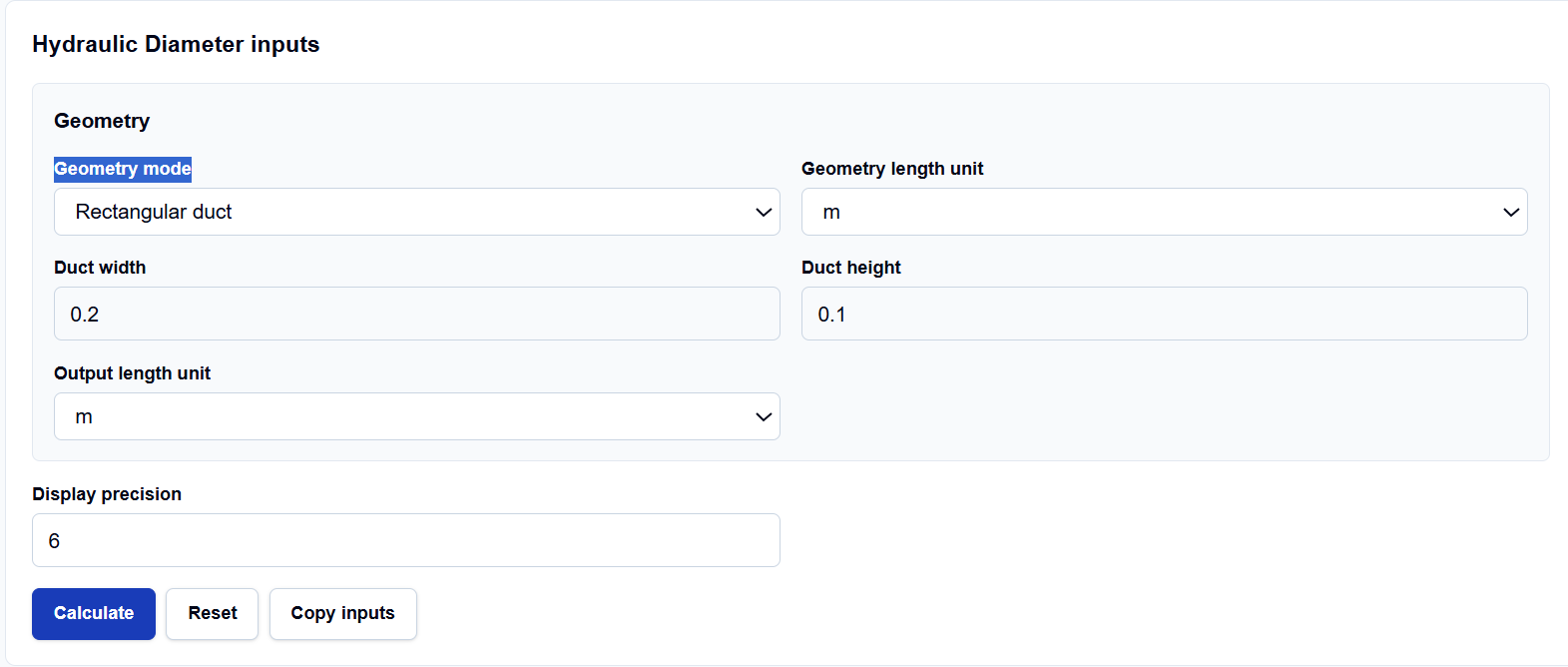
The interface is structured to let you choose the geometry mode that matches your specific design data. I have noticed that it processes everything locally in your browser, which is vital when you are handling proprietary dimensions for a sensitive project.
1. Standard Geometry Modes
You can select from Circular pipe, Rectangular duct, Square duct, or Concentric annulus. For a rectangular duct, you enter the width ($a$) and height ($b$). For an annulus, you provide the outer ($D_o$) and inner ($D_i$) diameters.
2. Custom Input Modes
If your section is irregular like a triangular cooling fin or a hex-head passage you can select Custom area and wetted perimeter. This mode allows you to enter the pre-calculated area and the specific length of the boundary in contact with the fluid ($P_w$).
3. Units and Precision
The tool supports a wide array of Geometry length units, ranging from micrometers (µm) to feet (ft). You can also control the Display precision and choose a different Output length unit, which is a major time-saver when converting manufacturer specs into SI units for your solver.
How I Use the Tool
My typical workflow starts with the Geometry mode selection. If I am working on a 200 mm by 100 mm rectangular duct, I enter those values and set the units to mm.
I then click the Calculate action button. One thing I’ve observed that is extremely helpful is the Unit-normalization summary. After clicking, the tool shows exactly how it converted my mm inputs into SI meters ($m$ and $m^2$) before performing the final math. This “receipt” allows me to audit the tool’s internal logic and ensures I didn’t miss a decimal point during data entry.
Once I have the result, I use the provided transfer link to send the resulting $D_h$ directly to the Reynolds Number Calculator. This seamless flow between tools minimizes the risk of transcription errors.
Understanding the Results
The primary result is the Hydraulic diameter ($D_h$), presented clearly at the top. Beneath it, the Secondary results provide the Cross-sectional area, Wetted perimeter, and the Aspect ratio.
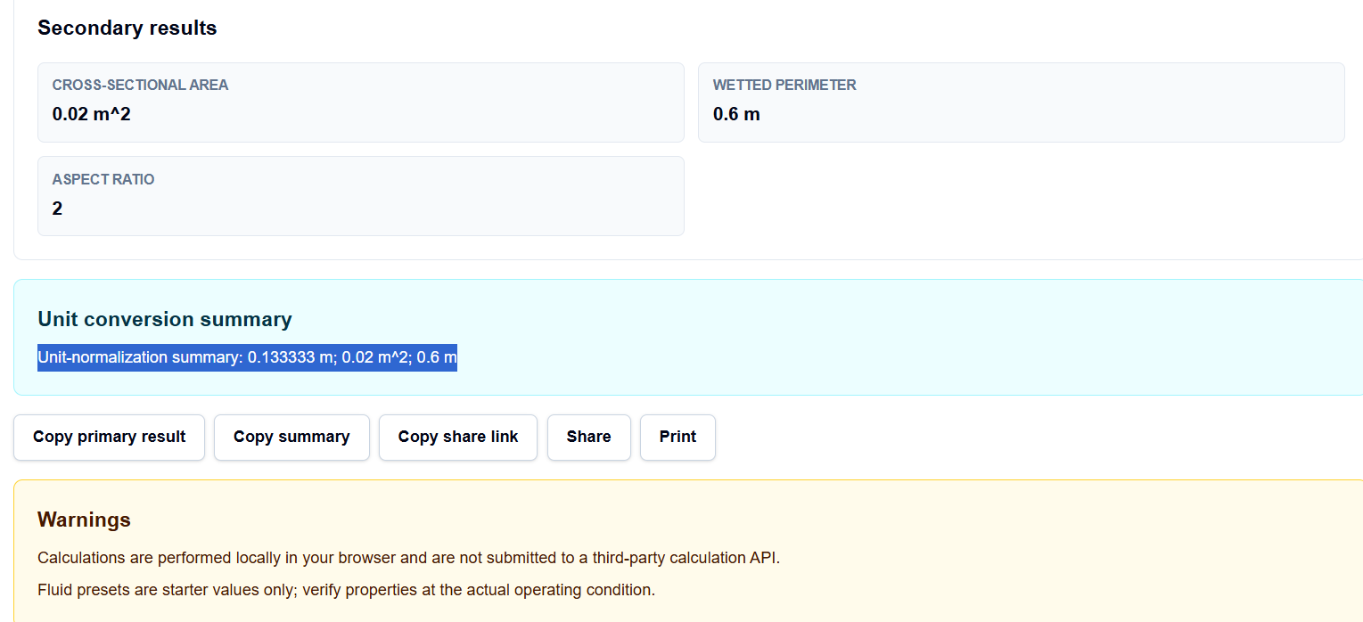
What I find useful for reporting is the Calculation steps section. It displays the explicit formula used such as $D_h = 2ab / (a + b)$ for a duct alongside the substituted values. This transparency is essential for educational purposes and for documenting the “Assumptions” behind a CFD setup.
A Practical Example
Suppose I am analyzing flow through an annulus with an outer diameter of 100 mm and an inner diameter of 60 mm. I select the “Concentric annulus” mode and enter 0.1 and 0.06 meters.
When I click calculate, the tool resolves the geometry to a hydraulic diameter of 0.04 m (or 40 mm). It also reminds me in the “Assumptions” section that the wetted perimeter includes only walls in contact with the fluid. This resulting 40 mm is the value I would then use as my characteristic length when calculating the Reynolds number for that specific annular passage.
Mistakes I Would Avoid
One major pitfall is including non-wetted boundaries. For example, in some open-channel scenarios, the top surface of the fluid is a free boundary, not a wall. The tool assumes a closed internal passage, so if you are using it for an open channel, you must manually adjust the wetted perimeter to exclude the free surface.
Another common error is mixing units. If you enter your area in square inches but your perimeter in centimeters without normalization, the resulting $D_h$ will be meaningless. I always rely on the tool’s built-in Unit System toggles to keep everything consistent in SI internally.
Try the Free Hydraulic Diameter Calculator
Before you hit “Initialize” on your next simulation, take a minute to verify your geometric length scales. It is the most reliable way to ensure your non-circular simulations are grounded in physical reality.
Try the Hydraulic Diameter Calculator here.
For a complete setup review, you can also explore the Reynolds Number Calculator to define your flow regime or the Friction Factor Calculator to estimate your expected pressure drop.
FAQ
1. Is hydraulic diameter the same as pipe diameter?
For a full circular pipe, yes. For non-circular passages like rectangular ducts or annuli, it is a derived value based on the ratio of area to wetted perimeter ($D_h = 4A/P_w$).
2. Why does an annulus use $D_o – D_i$ for its hydraulic diameter?
In a concentric annulus where both the inner and outer walls are in contact with the fluid, the math simplifies to $D_h = D_o – D_i$. This accounts for the increased wetted perimeter relative to the cross-sectional area.
3. Does this tool automatically adjust for open-channel flows?
No. This tool is designed for internal CFD passages. For open channels, the “wetted perimeter” must exclude the free surface. You can use the Custom mode to enter the area and the specific wetted wall length to find the hydraulic diameter for those cases.