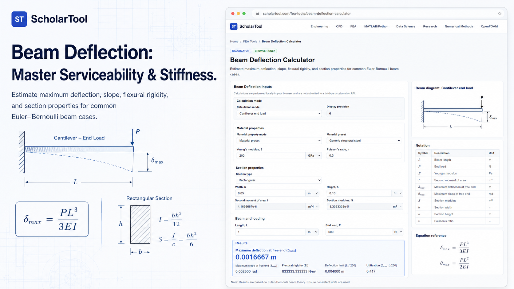
Beam Deflection Calculator: Euler-Bernoulli Stiffness Tool
When I am auditing a structural design, I often find that strength is only half the battle. A component might survive the peak Von Mises demand without yielding, but if it deflects too much, it can cause interference, vibration, or misalignment in a complex assembly. In professional engineering reports, documenting these “serviceability” limits is a requirement. As Dominique Madier notes in FEA Academy’s guidelines, performing preliminary estimations and mathematical checks is an essential step for verifying a model’s validity.
What I find indispensable for these stiffness checks is the Beam Deflection Calculator from ScholarTool. It is a deterministic, browser-local utility designed to resolve deflection and slope for common load cases. Whether I am sizing a support rail or grounding a high-fidelity Finite Element Analysis (FEA) result in physical reality, this tool ensures my stiffness assumptions are mathematically sound while keeping my proprietary project data private.
What the Beam Deflection Calculator Helps You Do
In technical terms, this tool applies the Euler-Bernoulli beam theory to identify the maximum displacement of a prismatic member. The primary purpose is to help you determine if a beam meets specific deflection criteria before you commit to detailed CAD or solver-intensive simulations.
I find the interface particularly useful because it provides a “Comparative Perspective” between load distributions. You can quickly toggle between point loads and uniform distributed loads (UDL) to see how the deflection profile shifts. The calculator removes the risk of manual integration errors by providing a “browser-only” engine. Because the math happens locally on your device, your sensitive manufacturing specs or proprietary material constants are never submitted to a third-party calculation API—a critical security requirement for professional technical documentation.
Inputs You Can Use
The interface is built with a logical, “case-first” layout that allows you to configure the tool based on the physical constraints of your assembly.
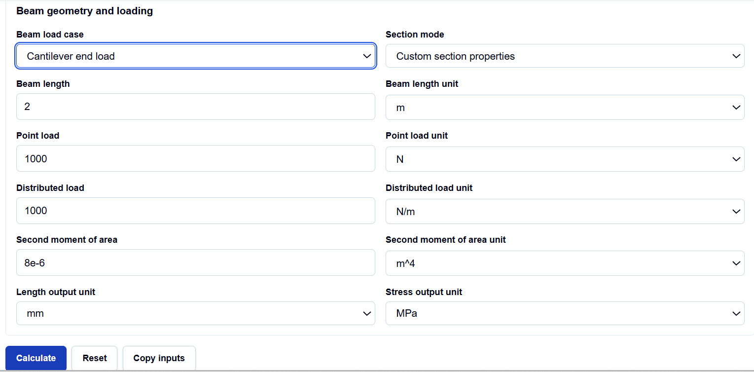
Beam Load Cases
I start by selecting the Beam load case that matches my assembly. You can choose from:
- Cantilever end load: For members fixed at one end and loaded at the tip.
- Cantilever UDL: For beams with a uniform weight distribution.
- Simply supported center load: For beams supported at both ends with a central point force.
- Simply supported UDL: The classic “distributed load on a span” case.
Section and Material Properties
Once the case is set, you enter your Bending moment or load components. I particularly appreciate the Section mode flexibility. You can choose Rectangular, Circular, Hollow circular, or Symmetric I-section to have the tool derive the Second Moment of Area ($I$) for you. If you already have a verified property from a CAD tool or standard table, you can select the Custom I mode. You then provide the Young’s modulus ($E$) and Beam length ($L$) using consistent SI units.
How I Use the Tool
My typical workflow begins by extracting the peak load and span from my design requirements. For instance, if I am designing a structural bracket for an aerospace application, I select the “Cantilever end load” case.
Once I enter the loads and geometry, I click calculate. I appreciate the transparency of the Calculation steps section. It explicitly shows the resolved flexural rigidity ($EI$) and the specific coefficient ($C$) used in the standard deflection formula. Because the calculations are performed locally in your browser using TypeScript, I can perform these audits in high-security environments without fear of data leakage. After the check, I use the “Use stress in Factor of Safety Calculator” link to move my data directly into a yielding check, completing the multi-disciplinary audit.
Understanding the Results
The result section provides the Maximum deflection ($\delta$) and Beam slope ($\theta$) prominently. However, for professional validation, the secondary outputs are often more critical:
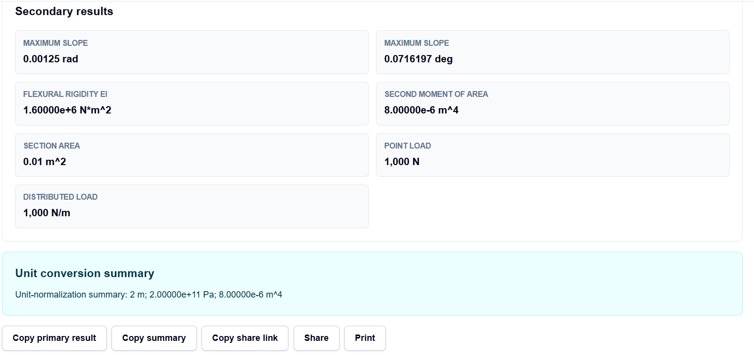
- Flexural rigidity ($EI$): The material-geometric product that characterizes the beam’s overall resistance to bending.
- Formula notation: A breakdown of the symbols used (P, w, EI, etc.), making the results easy to translate into a formal report.
I find the Calculation steps indispensable. They act as a “math receipt,” showing me exactly how the tool resolved the beam case and section properties before arriving at the final deflection value. This allows me to include the analytical “proof” alongside my simulation results.
A Practical Example
Suppose I am verifying a cantilevered steel support where the length is 2 m, the Young’s modulus is 200 GPa, and the section has a second moment of area of 8e-6 m⁴. If a tip load of 1000 N is applied, I select the “Cantilever end load” mode and enter these values.
When I click calculate, the tool applies the formula ($\delta = PL^3 / 3EI$) and returns a maximum deflection of approximately 0.00167 m (or 1.67 mm). If I then change the load to a UDL of 1000 N/m, the tool instantly resolves the deflection to 0.00125 m, allowing me to see the stiffness benefit of distributing the weight.
Mistakes I Would Avoid
One common pitfall is ignoring the small-deflection assumption. As the tool’s assumptions section warns, these formulas are based on linear Euler-Bernoulli theory. If your beam is deflecting more than roughly 10% of its length, the geometry becomes non-linear, and this tool will provide a non-conservative estimate.
Another mistake is mixing units. While the tool is deterministic, it requires consistency. I always ensure my loads are in Newtons and my lengths are in meters before entering them into the tool to prevent the “decimal drift” that can ruin a design audit.
Try the Free Beam Deflection Calculator
Before you finalize your next structural layout or spend hours refining a mesh for a simple stiffness check, take a minute to verify your baseline deflection. It is the fastest way to ensure your serviceability assumptions are physically grounded.
Try the Beam Deflection Calculator here.
To complete your structural audit, you may also find the Beam Bending Stress Calculator, Buckling Load Calculator, or the Shaft Design Calculator essential for your workflow.
FAQ
1. Does this tool support multiple point loads on a single beam?
No. As the tool documentation explicitly states, it supports one standard single-load case at a time. For multiple loads, you would typically use superposition or a full FEA solver.
2. Can I use this for a beam with a non-uniform cross-section?
No. The calculator assumes a prismatic beam with a constant second moment of area ($I$). If your beam is tapered, these analytical formulas will not be accurate.
3. Is my proprietary project data safe when using this tool?
Yes. This calculator is “browser-only,” meaning all mathematics are performed locally on your computer using TypeScript. Your inputs and results are never submitted to any external server or calculation API.