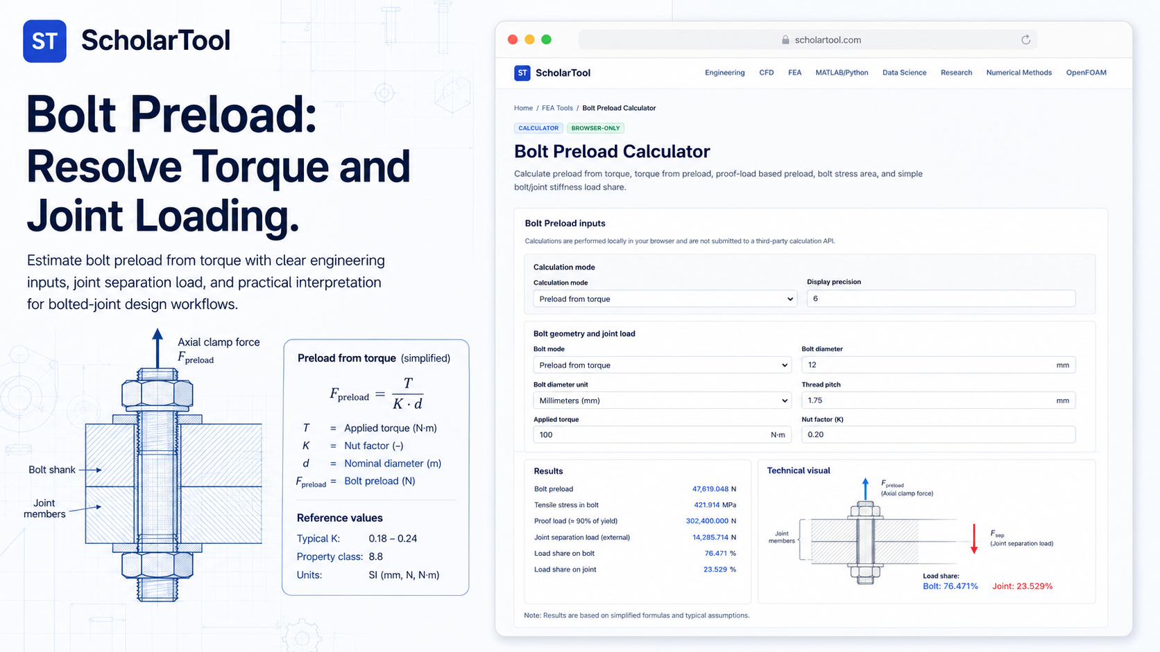
Bolt Preload Calculator: Torque & Joint Load Tool
When I am auditing a structural assembly or preparing a Finite Element Analysis (FEA) model, the bolts are often the most misunderstood components in the load path. As Dominique Madier emphasizes in FEA Academy’s guidelines, bolts are rarely modeled with 3D elements because we are primarily interested in the load transfer, not the local stress gradients near the threads. In professional practice, translating a tightening torque into a deterministic clamping force is a requirement for preventing joint separation and fatigue failure.
What I find indispensable for these foundational checks is the ScholarTool Bolt Preload Calculator. It is a deterministic, browser-local utility designed to solve the torque-preload relationship and joint load sharing equations. Whether I am sizing fasteners for a heavy machinery frame or grounding a simulation report in physical reality, this tool ensures my clamping assumptions are mathematically sound while keeping my proprietary project data private.
What the Bolt Preload Calculator Helps You Do
In technical terms, bolt preload is the internal “stretch” or clamping force created by tightening a fastener. The primary purpose of this calculator is to identify how much of that stretch you actually achieve for a given torque, and how that load changes when external forces are applied to the joint.
I find the interface particularly helpful because it provides a “Comparative Perspective” between tightening methods and design limits. You can calculate the Preload from torque (the common field check), or use the Proof preload mode to find the maximum safe clamp based on the material’s proof stress. The calculator removes the risk of manual derivation errors by providing a “browser-only” engine. Because the math happens locally on your device, your sensitive manufacturing specs or proprietary joint stiffnesses are never submitted to a third-party calculation API.
Inputs You Can Use
The interface is built with a logical, “mode-first” layout that allows you to configure the tool based on the specific assembly constraints you have.
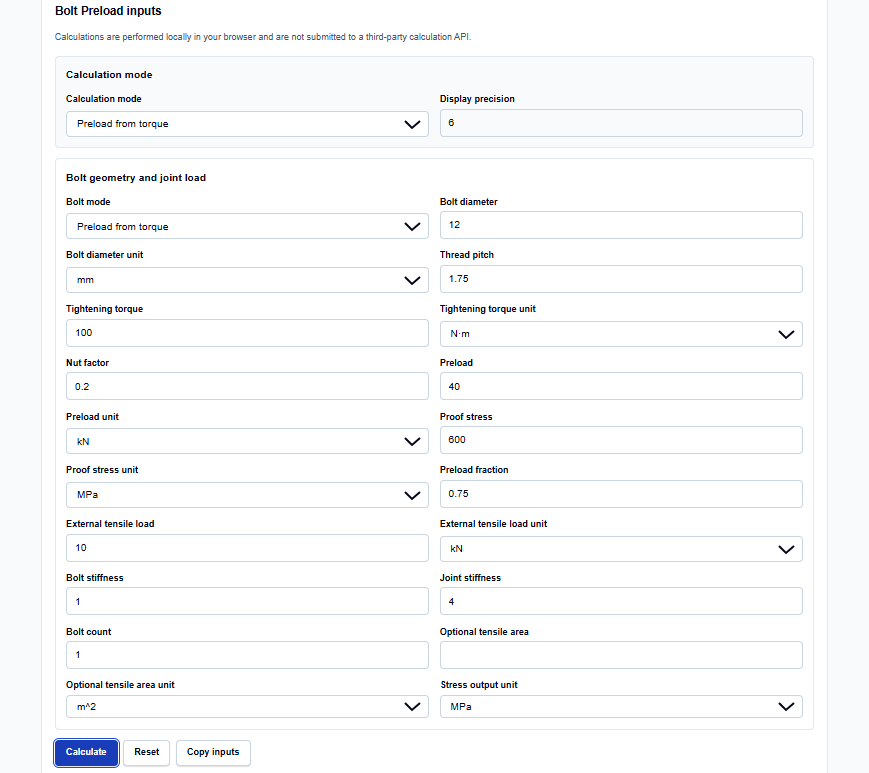
Calculation Modes
I start by selecting the mode that matches my task. You can choose from Preload from torque, Torque from preload, Proof preload, or Joint load share. I find the Joint load share mode vital for high-fidelity work, as it requires you to define the Bolt stiffness ($k_b$) and Joint stiffness ($k_j$) to see how much external load actually reaches the bolt.
Geometry and Loading
Once the mode is set, you enter your Bolt diameter and Thread pitch. The tool supports diverse units, including millimeters, inches, and even microns for precision instrumentation. You then provide the Tightening torque and the Nut factor ($K$). What I find professionally reassuring is that the tool explicitly labels $K$ as a user-entered empirical factor, as it can vary widely based on lubrication and coating.
How I Use the Tool
My typical workflow begins by extracting the peak tensile demand from a global FEA model. Since I often follow Madier’s advice and represent bolts as 1D beams or springs, I use this calculator to determine the initial load to apply to those elements.
Once I enter the geometry and material values, I click Calculate. I always review the Calculation steps section, which acts as a “math receipt” showing the derived Tensile stress area and the SI-normalized SI values used in the background. Because the calculations are performed locally in TypeScript, I can perform these audits in high-security environments without fear of IP leakage. After the check, I use the Copy summary button to archive the analytical proof directly in my design documentation.
Understanding the Results
The result section provides the Estimated preload from torque prominently at the top. However, for a professional audit, the secondary values are often more critical for validation:
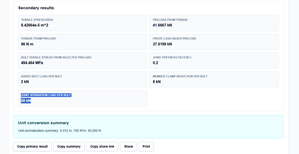
- Joint stiffness factor ($C$): The fraction of the external load that is added to the bolt.
- Member clamp reduction: Shows how much clamping force you lose when the joint is loaded.
- Joint separation load: The critical threshold where the parts no longer touch, indicating total joint failure.
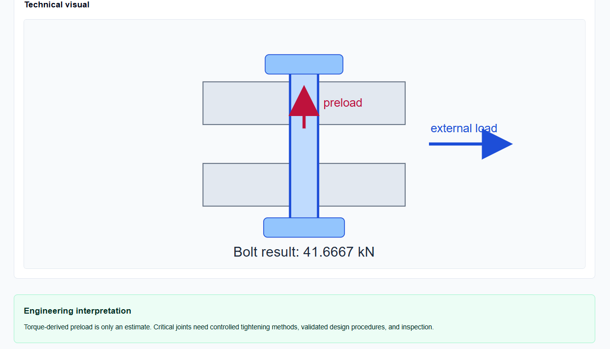
I find the Technical visual indispensable; it provides a diagram of a bolted joint with preload and external load labels, serving as a constant visual reminder of the concentric spring model used in the calculation.
A Practical Example
Suppose I am verifying a joint with a 12 mm bolt and a 1.75 mm pitch. I am applying a tightening torque of 100 N·m and using a standard nut factor of 0.2.
When I enter these values and click calculate, the tool resolves the stress area to approximately $8.42 \times 10^{-5}$ m² and returns an Estimated preload of 41.67 kN. If I then define a bolt-to-joint stiffness ratio of 1:4 ($C = 0.2$) and apply an external load of 10 kN, the tool instantly shows that the final bolt load is 42 kN, while the member clamping force has reduced by 8 kN. This allows me to verify that the joint remains closed with a separation margin of 50 kN.
Mistakes I Would Avoid
One common pitfall is ignoring torque-preload scatter. As the tool’s engineering interpretation warns, torque-derived preload is only an estimate. I never treat a calculated 41.67 kN as an absolute guarantee; for critical joints, I always specify controlled tightening methods or physical testing.
Another mistake is treating these results as a design certification. These are preliminary scalar mechanics checks. As the tool’s warnings remind us, it does not account for prying action, eccentricity, or gasket behavior. If your joint has offset loading or soft gaskets, you must use validated design standards like AISC or VDI 2230 in conjunction with these estimates.
Try the Free Bolt Preload Calculator
Before you finalize your next structural assembly or define your bolt loads in a solver, take a minute to verify your clamping margins. It is the fastest way to ground your joint reliability in physical reality.
Try the Bolt Preload Calculator here.
To complete your structural audit, you may also find the Weld Strength Calculator, Factor of Safety Calculator, or the Stress Converter essential for your workflow.
FAQ
1. What is the “Nut Factor” (K) used in the torque formula?
The nut factor is an empirical coefficient that accounts for the friction in the threads and under the bolt head. It is affected by lubrication, plating, and thread condition. A common value for “as-received” steel is 0.2, but this should be verified for your specific hardware.
2. Can this tool account for prying action on the bolt?
No. As noted in the tool’s explicit warnings, this is a preliminary scalar mechanics check and does not include prying, eccentricity, or gasket relaxation effects. These must be checked separately using applicable bolting standards.
3. Is my proprietary manufacturing data safe when using this tool?
Yes. All calculations are performed locally in your browser using TypeScript. Your inputs and results are never submitted to any external server or third-party calculation API.