
First Cell Height Calculator: Target Y Plus & Wall Meshing Tool
When I am setting up a Computational Fluid Dynamics (CFD) simulation whether it is a internal pipe flow study or a complex external aerodynamics model the boundary layer mesh is the single most important factor for both convergence and physical accuracy. As M. Ramkrishna from IITM notes, grid generation is not just about making a mesh; it is about asking how that mesh represents the underlying mathematical model. If the first cell at the wall is too large, your turbulence model may fail to capture the viscous sublayer physics; if it is too small, you waste precious computational resources on unnecessary resolution.
What I find indispensable for balancing these requirements is the First Cell Height Calculator from ScholarTool. It is a deterministic, browser-local utility designed to resolve the dimensionless wall distance ($y^+$) into tangible geometric dimensions. Whether you are defining boundary conditions for OpenFOAM or auditing a mesh in Ansys, this tool ensures your near-wall spacing is physically grounded without ever submitting your proprietary parameters to an external server.
What the First Cell Height Calculator Helps You Do
The primary purpose of this tool is to bridge the gap between abstract turbulence requirements and geometric mesh dimensions. In technical terms, it estimates the physical height of the first near-wall cell required to satisfy a specific “Target $y^+$”. From a comparative perspective, this is critical because different turbulence treatments have different needs: “low-Reynolds” models (like $k$-$\omega$ SST) often require $y^+ \approx 1$ to resolve the sublayer, while wall-function models (like $k$-$\epsilon$) typically require $y^+ > 30$ to stay in the log-law region.
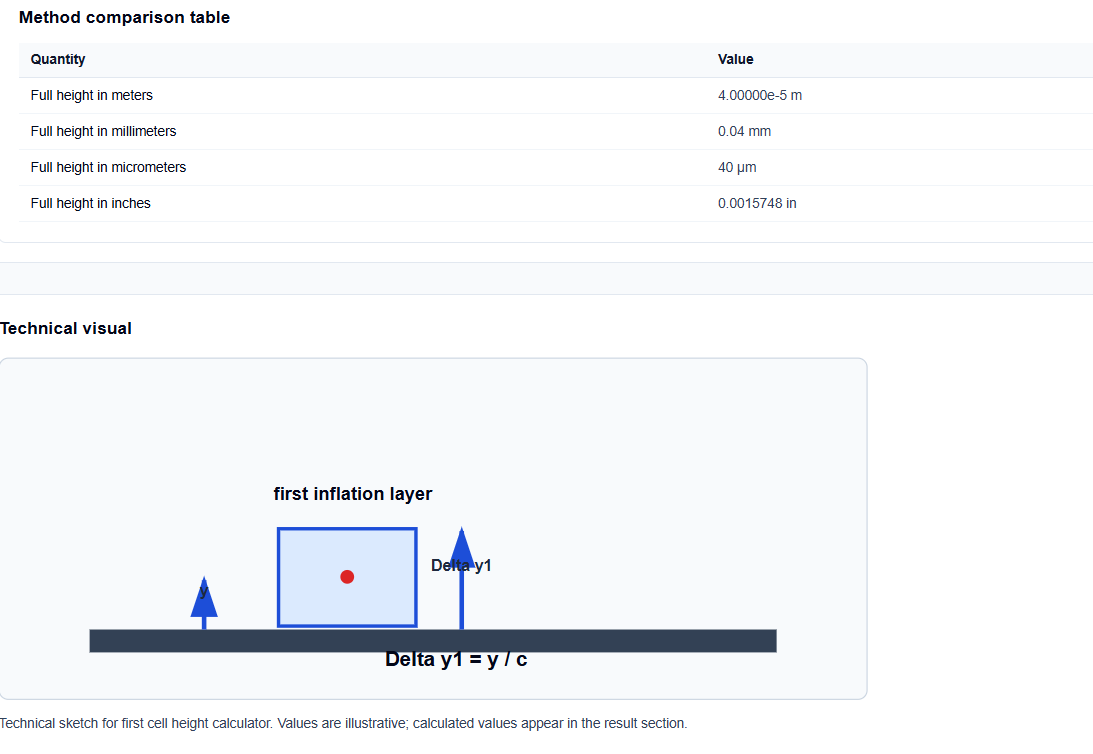
I find the interface particularly helpful because it explicitly distinguishes between the Wall-to-cell-centre distance ($y$) and the Full first-layer height ($\Delta y_1$). In my experience, forgetting that $y^+$ is defined relative to the cell center is one of the most common sources of meshing error. The ScholarTool interface automates this logic, allowing you to plan your inflation layers with high confidence.
Inputs You Can Use
The interface is built with a modular layout, allowing you to configure the calculator based on the data you already have from your initial flow analysis.
Fluid Properties
I start by selecting the Fluid property mode. You can use presets for Water near 20 °C or Air near 20 °C for quick estimates. If your simulation involves non-standard temperatures or pressures, you can switch to Manual properties to enter density and either dynamic or kinematic viscosity directly.
Wall Treatment and Friction Velocity
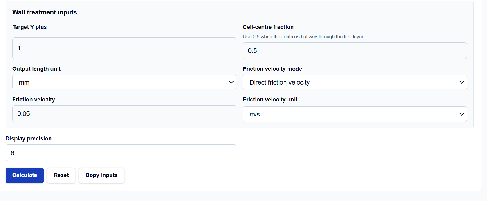
This is where I find the tool really shines. It offers four distinct Friction velocity modes to calculate $u_\tau$:
- Direct friction velocity: Use this if you have already calculated $u_\tau$ from an external source.
- Wall shear stress and density: Ideal when you have experimental shear data ($\tau_w$).
- Bulk velocity and Darcy friction factor: Perfect for pipe flow where you have resolved the friction factor using a tool like the Friction Factor Calculator.
- Bulk velocity and skin-friction coefficient: Standard for external boundary layer work.
You also specify your Target Y plus and the Cell-centre fraction ($c$). The default is 0.5, representing a cell center at the geometric midpoint of the layer.
How I Use the Tool
My typical workflow starts with the friction velocity mode. If I am auditing an internal flow simulation, I select “Bulk velocity and Darcy friction factor.” I enter my bulk velocity (e.g., 2 m/s) and my $f_D$ (e.g., 0.02).
Once I enter my Target Y plus (let’s say 1 for a high-fidelity run), I click Calculate. I appreciate that the tool is “browser-only,” meaning the calculations are performed locally on my machine using TypeScript. This ensures that sensitive manufacturing dimensions or proprietary fluid specs are never uploaded to a third-party API. After reviewing the primary result, I use the Copy summary button to archive the SI-normalized “receipts” of the math in my meshing log.
Understanding the Results
The result section provides the Full first-cell height prominently at the top. Below that, the Secondary results break down the derived Wall-to-cell-centre distance and the friction velocity used.
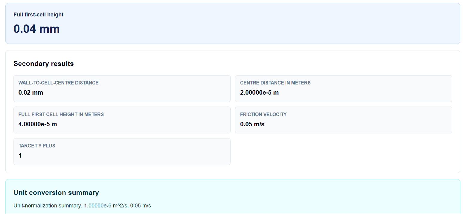
What I find most useful for multi-unit workflows is the Method comparison table. It displays the full height in meters, millimeters, micrometers, and inches simultaneously. If I am using a CAD-based mesher that expects microns but my solver report is in meters, I can glance at this table for an instant “sanity check.” I also value the Technical visual, which provides a sketch labeling $y$ and $\Delta y_1$, serving as a visual reminder of the cell-centre relationship.
A Practical Example
Suppose I am verifying a mesh for water flow where my calculated friction velocity is 0.05 m/s and my target $y^+$ is 1. I use the “Water near 20 °C” preset, which pulls in a kinematic viscosity of $1 \times 10^{-6}$ m²/s.
When I click calculate, the tool resolves the formulas ($y = 1 \times 10^{-6} / 0.05$ and $\Delta y_1 = y / 0.5$) to return a Full first-cell height of 0.04 mm. I can then look at the comparison table to see that this is equivalent to 40 µm, allowing me to set my inflation layer height in my meshing software accurately.
Mistakes I Would Avoid
One common pitfall I see is assuming a $y^+$ of 1 is always required. As the tool’s common mistakes section notes, the target depends entirely on your turbulence model and wall treatment strategy. Always consult your solver’s documentation first.
Another mistake is forgetting to check the “achieved” $y^+$ after solving. This calculator provides a pre-solve estimate. Because local wall shear can vary strongly over a surface, the cell height that works at the inlet might not satisfy the target at a separation point. I always follow up a simulation by using the Y Plus Calculator to verify the actual results.
Try the Free First Cell Height Calculator
Before you finalize your boundary layer mesh or hit “Initialize” on your next CFD run, take a minute to verify your cell spacing. It is the fastest way to ensure your wall resolution is physically sound.
Try the First Cell Height Calculator here.
To complete your simulation setup, you may also find the Reynolds Number Calculator, Friction Factor Calculator, or the Turbulence Intensity Calculator essential for your workflow.
FAQ
1. Is wall distance ($y$) the same as the full height of the first cell?
No. In this tool, $y$ represents the distance from the wall to the cell center. The full height ($\Delta y_1$) depends on the cell-centre fraction ($c$). By default ($c=0.5$), the full height is twice the center distance.
2. Can I use this tool for both air and water simulations?
Yes. The calculator includes built-in presets for air and water near 20 °C, or you can manually enter custom properties for any fluid to accommodate different operating conditions.
3. Does this tool guarantee my $y^+$ will be exactly as calculated?
No. This is a pre-solve estimate. Because local wall shear stress can vary spatially over your geometry, you must check the achieved $y^+$ in your CFD solver after the simulation has run.