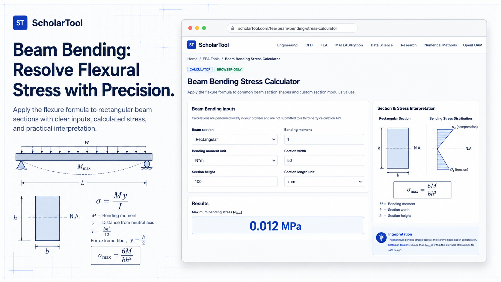
Beam Bending Stress Calculator: M/S & Flexure Tool
When I am starting a new structural design or auditing a complex Finite Element Analysis (FEA) model, I rarely jump straight into the solver. As noted in professional guidelines for good modeling practices, documenting mathematical checks and performing preliminary estimations are essential steps for verifying a model’s validity. Before I trust a nodal stress probe from a shell element simulation, I want to know what the theoretical extreme fiber stress should be based on the fundamental flexure formula.
What I find indispensable for these foundational checks is the Beam Bending Stress Calculator from ScholarTool. It is a deterministic, browser-local utility designed to apply the flexure formula to common prismatic beam sections. Whether I am sizing a support bracket or grounding an experimental report in physical reality, this tool ensures my initial stress estimates are mathematically sound while keeping my proprietary project data private.
What the Beam Bending Stress Calculator Helps You Do
In technical terms, bending stress is the normal stress induced in a structural element when it is subjected to an external load applied perpendicularly to its longitudinal axis. The primary purpose of this tool is to identify the extreme-fiber bending stress ($\sigma$) the maximum stress occurring at the furthest distance from the neutral axis. As I have observed in standard mechanics of materials texts like Hibbeler or Shigley, this is a fundamental requirement for determining if a beam will yield under a specific moment.
The ScholarTool interface provides a unified environment where diverse inputs ranging from legacy Imperial units like $lbf\cdot in$ to modern SI Megapascals can be harmonized. What I appreciate most is that the tool processes everything “browser-only”. Your sensitive simulation parameters or proprietary section dimensions are processed locally on your machine and are never submitted to a third-party calculation API a critical security requirement for high-stakes technical documentation.
Inputs You Can Use
The interface is built with a logical, “shape-first” layout that allows you to configure the tool based on the geometry you are analyzing.
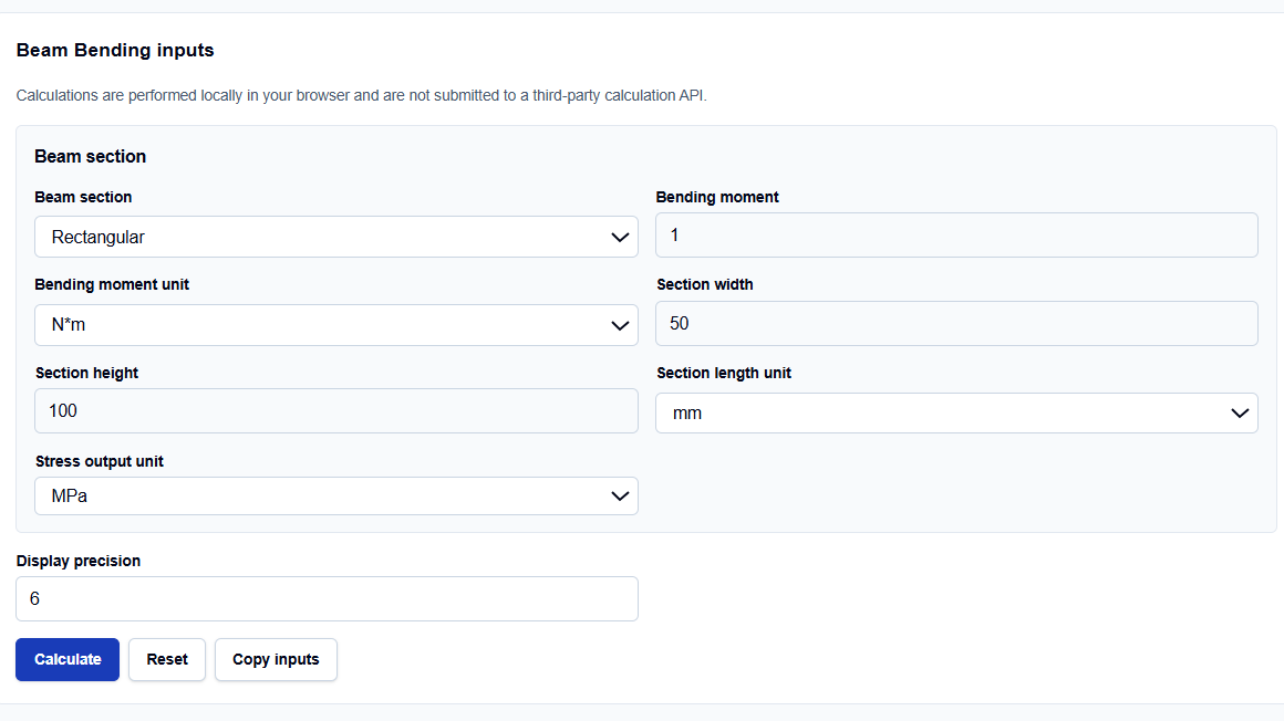
Beam Section Modes
I start by selecting the Beam section that matches my design. You can choose from Rectangular, Solid circular, Hollow circular, or Custom section properties. I find the Custom mode particularly useful because it allows me to enter a known section modulus ($S$) or a second moment of area ($I$) directly from a manufacturer’s table, bypassing the need for manual geometric derivation.
Moment and Geometry Data
Once the mode is set, you enter your Bending moment ($M$) and your section dimensions, such as Section width ($b$) and Section height ($h$). The tool supports four distinct units for bending moments and six for length, ranging from micrometers ($\mu m$) for precision medical devices to feet ($ft$) for civil structures. What I find helpful is the Display precision toggle (up to 6 decimals), which ensures that rounding errors do not compromise my audit trail.
How I Use the Tool
My typical workflow begins by extracting the peak bending moment from my global FEA model or a shear-moment diagram. For instance, if I am looking at a simple support beam, I select the “Rectangular” mode.
Once I enter the values, I click Calculate. I appreciate the transparency of the Calculation steps section. It explicitly shows the resolved section properties and how the section modulus was derived before arriving at the final stress result. Because the calculations are performed locally in your browser using TypeScript, I can audit sensitive manufacturing specs without fear of data leakage. After the check, I often use the “Use stress in Factor of Safety Calculator” link to send the result directly to the yielding check utility, completing the uniaxial stress comparison.
Understanding the Results
The result section provides the Extreme-fiber bending stress prominently at the top. However, for professional reporting, the Secondary results are often more critical for validation:
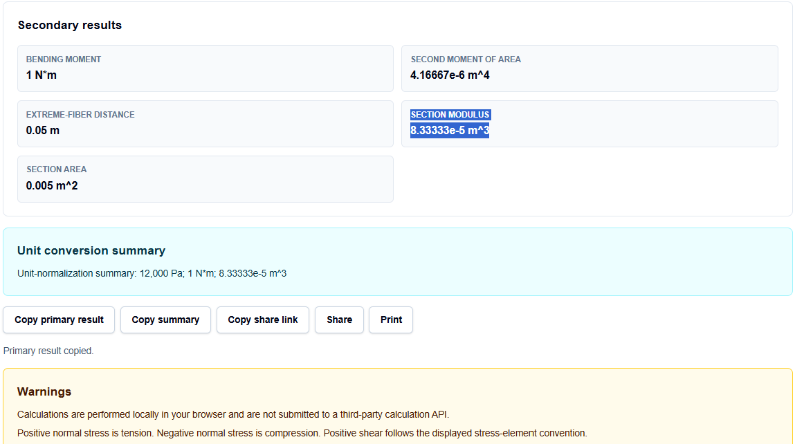
- Second moment of area ($I$): The geometric resistance to bending.
- Extreme-fiber distance ($c$): The distance from the neutral axis to the top or bottom surface.
- Section modulus ($S$): The ratio $I/c$, which characterizes the section’s strength.
- Section area ($A$): Useful for weight and mass estimates.
I also find the Unit-normalization summary indispensable. It acts as a “math receipt,” showing me exactly what base SI values were used to reach the result, making it easy to include in a design review.
A Practical Example
Suppose I am verifying a rectangular aluminum beam with a 50 mm width and a 100 mm height, subjected to a bending moment of 1 N*m.
When I enter these dimensions and click calculate, the tool resolves the second moment of area to approximately 4.16667e-6 $m^4$ and returns an extreme-fiber bending stress of 0.012 MPa. This immediate resolution allows me to verify that the stress is negligible before I commit to a more complex non-linear simulation.
Mistakes I Would Avoid
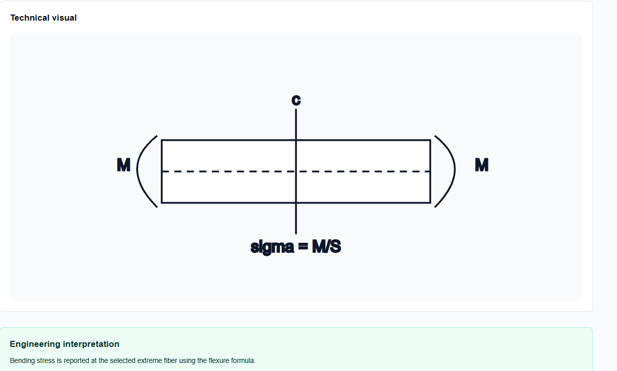
One common pitfall is using the wrong bending axis. As the tool’s common mistakes section warns, you must ensure the entered dimensions align with the axis about which the moment is acting. The tool’s Technical visual helps here by providing a sketch that labels the relationship between the moment and the section height.
Another mistake is treating this as a deflection or buckling check. This tool strictly calculates flexural stress. As noted in the assumptions, it assumes a straight prismatic beam and linear elastic distribution. If your design is prone to lateral torsional buckling or requires a deflection limit check, you must use supplementary solvers as this tool does not include code-specific safety checks.
Try the Free Beam Bending Stress Calculator
Before you finalize your next structural report or initialize a long-running FEA solver, take a minute to verify your flexural demands. It is the fastest way to ensure your structural assumptions are physically grounded.
Try the Beam Bending Stress Calculator here. To complete your structural audit, you may also find the Factor of Safety Calculator, Stress Converter, or Material Property Converter essential for your workflow.
FAQ
1. What formula does this beam calculator use?
It uses the standard flexure formula $\sigma = Mc / I$, where $M$ is the bending moment, $c$ is the distance to the extreme fiber, and $I$ is the second moment of area. This can also be expressed as $\sigma = M / S$, where $S$ is the section modulus.
2. Can I use this tool for a hollow pipe?
Yes. You should select the “Hollow circular” mode, which allows you to enter both the outer and inner diameters to resolve the correct section properties.
3. Does this tool calculate beam deflection?
No. This specific calculator focuses strictly on bending stress. Deflection, shear, and buckling are not solved by this tool and must be verified separately using applicable standards.