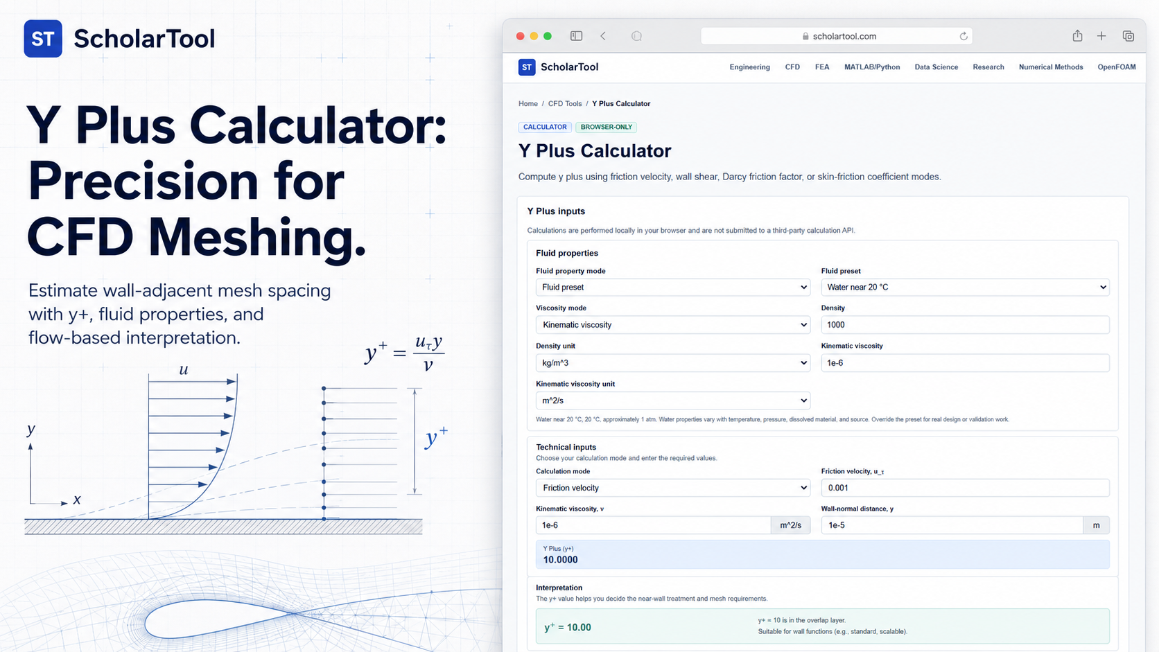
Y Plus Calculator: CFD Wall Meshing & u-tau Tool
When I am setting up a Computational Fluid Dynamics (CFD) simulation whether it is an internal pipe flow study or an external aerodynamics model the boundary layer mesh is the single most important factor for convergence and accuracy. If the first cell at the wall is too large, the turbulence model might fail to capture the physics of the viscous sublayer. If it is too small, I might be wasting precious computational resources. As M. Ramkrishna from IITM notes, grid generation is not just about making a mesh; it is about asking how that mesh represents the underlying mathematical model.
What I find indispensable for balancing these requirements is the ScholarTool Y Plus Calculator. It is a deterministic, browser-local utility designed to resolve the dimensionless wall distance ($y^+$). Whether you are defining boundary conditions for OpenFOAM or auditing a mesh in Ansys, this tool ensures your wall-treatment assumptions are physically sound without ever submitting your proprietary parameters to a third-party API.
What the Y Plus Calculator Helps You Do
The primary purpose of this tool is to bridge the gap between geometric mesh dimensions and the dynamic flow regime near a solid boundary. In technical terms, $y^+$ is the ratio of inertial forces to viscous forces within the boundary layer. As the ScholarTool interface demonstrates, this single number dictates whether your first cell center resides in the viscous sublayer ($y^+ < 5$), the buffer layer ($5 < y^+ < 30$), or the log-law region.
I find this specifically useful for selecting turbulence models. For example, if I am using a “low-Reynolds” model like $k-\omega$ SST, I typically aim for $y^+ \approx 1$ to resolve the viscous sublayer directly. If I am using wall functions with a $k-\epsilon$ model, I need the first cell center to be in the log-law region ($y^+ > 30$). The calculator removes the manual derivation risk, providing the “Engineering interpretation” necessary to decide if your mesh is appropriate for your chosen solver.
A Comparative Perspective: Magnitude vs. Dimension
From a comparative perspective, it is useful to see how $y^+$ differs from a simple physical distance. While a Reynolds Number Calculator characterizes the entire flow field, the Y Plus Calculator characterizes the local interaction at the wall.
In my workflow, I think of this tool as the “Geometric Resolver.” You might know your bulk velocity and pipe diameter, but $y^+$ tells you how that velocity translates into shear at the surface. It is the dynamic counterpart to tools like the Hydraulic Diameter Calculator; while one defines the “where” of the passage, the other defines the “how” of the wall-fluid interface.
Inputs You Can Use
The interface is built with a modular, “data-available” layout. You can configure it based on exactly what parameters you already have from your initial flow analysis.
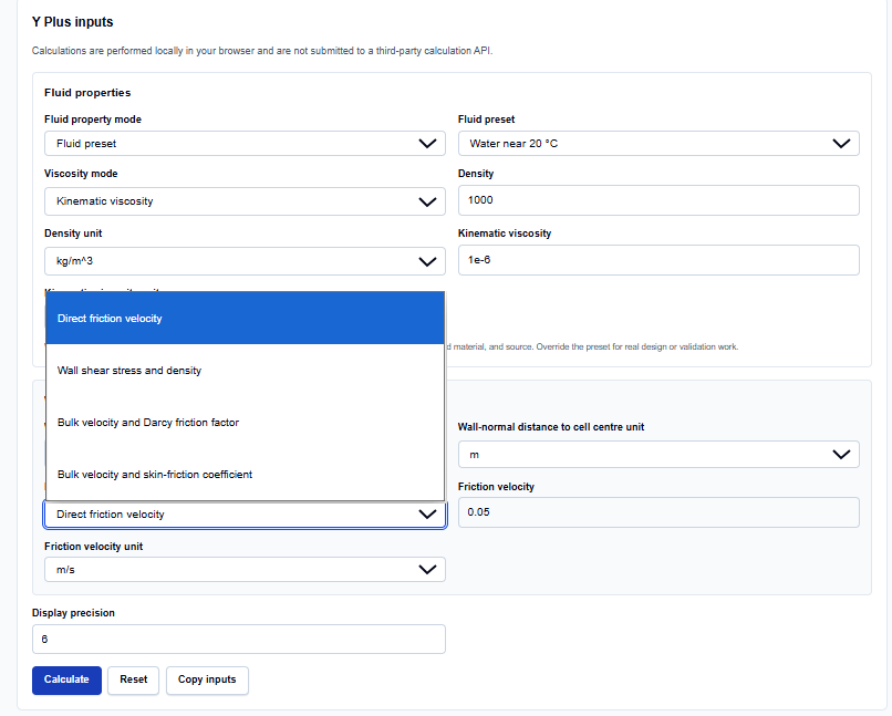
Fluid and Wall Data
I start by selecting the Fluid properties. I can use presets for Water or Air at 20 °C, which I find very helpful for quick estimates. Below this, I enter the Wall-normal distance to cell center. What I appreciate here is the support for six different units ranging from microns (µm) for high-fidelity boundary layers to feet (ft) for large-scale civil engineering models.
Friction Velocity Modes
The tool stands out because it offers four distinct Friction velocity modes:
- Direct friction velocity: When you already have $u_\tau$.
- Wall shear stress and density: Ideal when you have experimental shear data.
- Bulk velocity and Darcy friction factor: Perfect for pipe flow where you’ve used the Friction Factor Calculator.
- Bulk velocity and skin-friction coefficient: Standard for external boundary layer work.
How I Use the Tool
My typical workflow starts with the Friction Velocity Mode. If I’m auditing a pipe flow simulation, I select “Bulk velocity and Darcy friction factor” and enter the $f_D$ value I got from a Colebrook-White calculation.
Once I enter my wall distance (e.g., 0.2 mm), I click Calculate. I appreciate that the tool is “browser-only,” executing the TypeScript logic locally on my machine. This ensures that my sensitive simulation boundary conditions are never uploaded. After reviewing the result, I often use the “Use target in First Cell Height Calculator” link to determine exactly how thick my inflation layers should be to hit a specific target $y^+$.
Understanding the Results
The result section provides the Y plus value prominently. However, for professional documentation, I find the Secondary results and Calculation steps indispensable. The tool explicitly shows the derived friction velocity and the kinematic viscosity used.
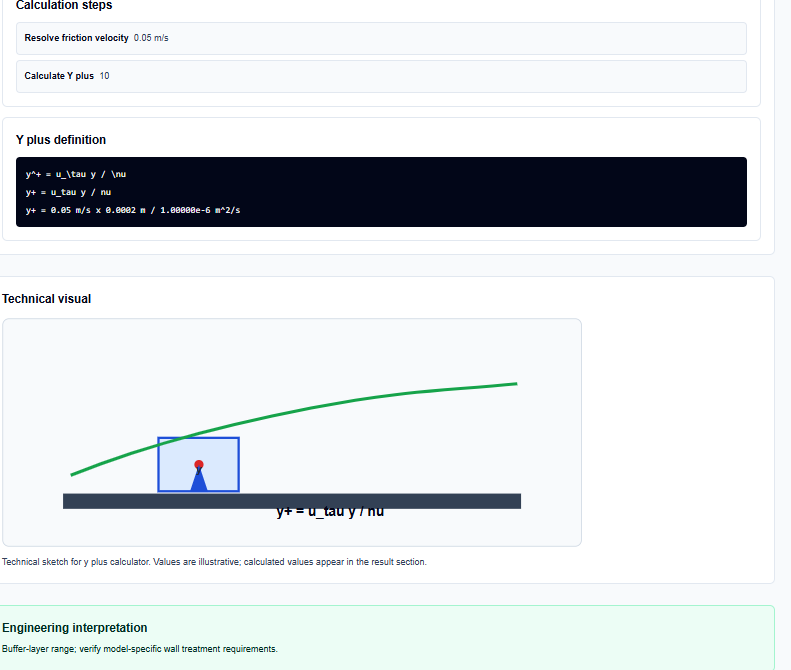
I also find the Technical visual helpful; it provides a sketch showing the relationship between the wall and the first cell center. This serves as a constant visual reminder that $y$ in the formula $y^+ = u_\tau y / \nu$ is the distance to the cell center, not the full thickness of the first mesh layer.
A Practical Example
Suppose I am verifying a mesh for water flow at 20 °C where my calculated friction velocity is 0.05 m/s. I have set my first cell center at 0.0002 m.
When I enter these into the calculator, it resolves the kinematic viscosity to approximately $1e-6$ $m^2/s$ and returns Y plus = 10. The Engineering interpretation instantly flags this as being in the buffer-layer range, which warns me that some standard wall-function strategies might be unsuitable for this mesh.
Mistakes I Would Avoid
One common pitfall is confusing wall distance with cell height. As the tool’s common mistakes section reminds us, $y$ is measured to the cell center. If your first layer is 1 mm thick, your wall distance input should likely be 0.5 mm.
Another mistake is confusing Darcy friction factor ($f_D$) with the skin-friction coefficient ($C_f$). As Bruce Hunt notes, these are mathematically related but distinct. Using the wrong coefficient mode in the calculator can lead to a significant error in your friction velocity, and subsequently, your $y^+$.
Try the Free Y Plus Calculator
Before you finalize your boundary layer mesh or hit “Initialize” on your next CFD run, take a minute to verify your wall spacing. It is the fastest way to ground your simulation in physical reality.
Try the Y Plus Calculator here.
To complete your simulation setup, you may also find the Reynolds Number Calculator, Friction Factor Calculator, or Turbulence Intensity Calculator essential for your workflow.
FAQ
1. Is wall distance ($y$) the same as the height of the first cell?
No. In most CFD solvers, $y$ is the distance from the wall to the center of the first cell. The total height of the first cell is typically twice this distance ($2y$), assuming the center is at the geometric midpoint.
2. What $y^+$ should I aim for in my CFD mesh?
It depends on your turbulence model. For near-wall modeling (resolving the sublayer), aim for $y^+ < 1$ or $y^+ < 5$. For wall functions, aim for $y^+ > 30$. The ScholarTool calculator provides an interpretation to help you identify these regions.
3. Does this tool calculate the friction factor for me?
The calculator has a mode to use the Darcy friction factor as an input to find $y^+$, but it does not calculate the friction factor itself. You should use the ScholarTool Friction Factor Calculator to find that value first.