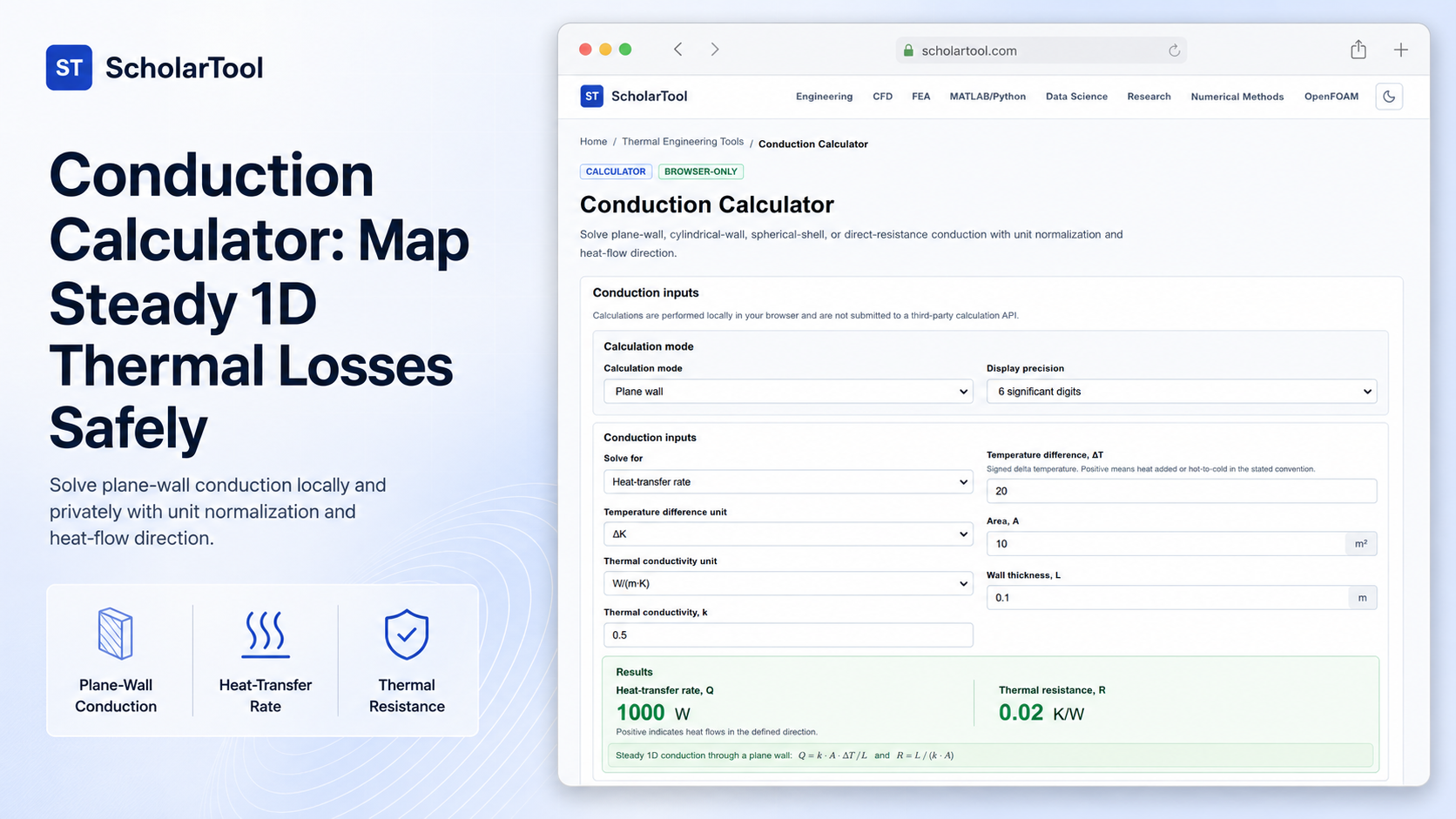
Conduction Calculator: Private Thermal Loss Sizer
When transitioning a thermofluid system layout from raw design coordinates to physical equipment, evaluating heat losses or barrier requirements is a major point of friction [156, 18.1]. Every mechanical engineer must determine the rate of heat energy moving through barriers like boiler tubes, furnace walls, or insulated piping [156, 18.2]. Guessing these conduction values without a structured planning receipt risks under-insulating critical components or over-specifying costly materials.
To bridge this diagnostic bottleneck with high accuracy and complete privacy, I use the Conduction Calculator from ScholarTool. This browser-local utility solves plane-wall, cylindrical-wall, spherical-shell, or direct thermal resistance equations. Because all calculations execute entirely in your local browser tab using client-side logic, your proprietary process dimensions and boundary conditions are never uploaded to any external database, ensuring 100% data sovereignty.
What the Conduction Calculator Helps You Do
The primary purpose of this tool is to act as a steady one-dimensional conduction takeoff aid during early process layout and insulation planning. Rather than requiring you to configure heavy finite element software, it organizes Fourier-law variables into a clean, auditable “math receipt”.
What I find useful here is that the tool accommodates both simple flat surfaces and complex radial geometries. You can choose the exact physical geometry that matches your system boundaries, and the interface automatically toggles the necessary coordinate fields. This allows you to evaluate thermal resistances and spatial heat flux values side-by-side.
Inputs You Can Use
The interface features a configuration-first layout to ensure your thermodynamic assumptions are sound before parsing begins:
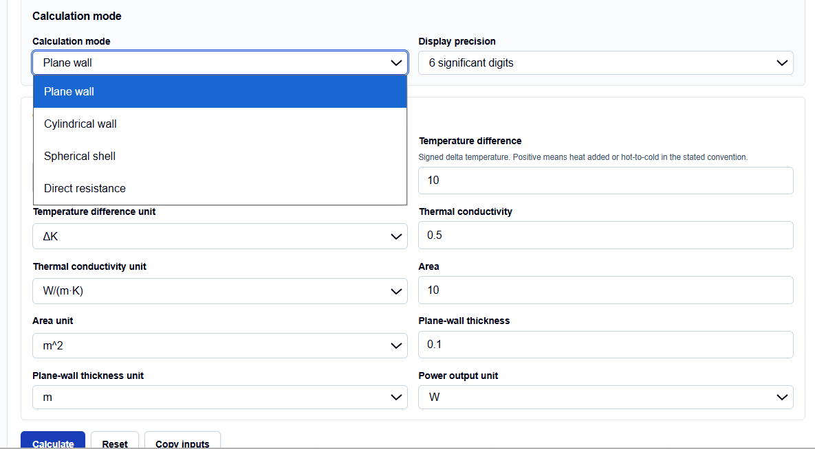
- Geometry Mode: You can choose between plane wall, radial cylinder, radial sphere, or direct thermal resistance depending on your boundary conditions.
- Thermal Conductivity (k): Enter the material’s conductivity in W/(m K). Thermal properties can vary significantly, so you must verify this property for the actual operating temperature.
- Signed Temperature Difference (Delta T): Temperature differences use delta units without absolute offsets.
- Geometric Parameters: Enter thickness and normal area for flat walls. For radial geometries, you enter inner and outer radii directly instead of mean area shortcuts.
How I Use the Tool
I open the Conduction Calculator on ScholarTool. First, select your geometry mode.
When I enter our raw design values into the inputs, I verify that they align with the expected parameters. If your data is available in this form, you can input the thermal conductivity and coordinates directly in the selected unit system. Once my parameters are set, I click the calculate button. All output summaries, visual plots, and secondary resistance values remain completely hidden until this action succeeds. If you edit any coordinate afterward, the results automatically hide to prevent stale data copy errors.
Understanding the Results
The result section helps you verify the heat flow by displaying several structured parameters:
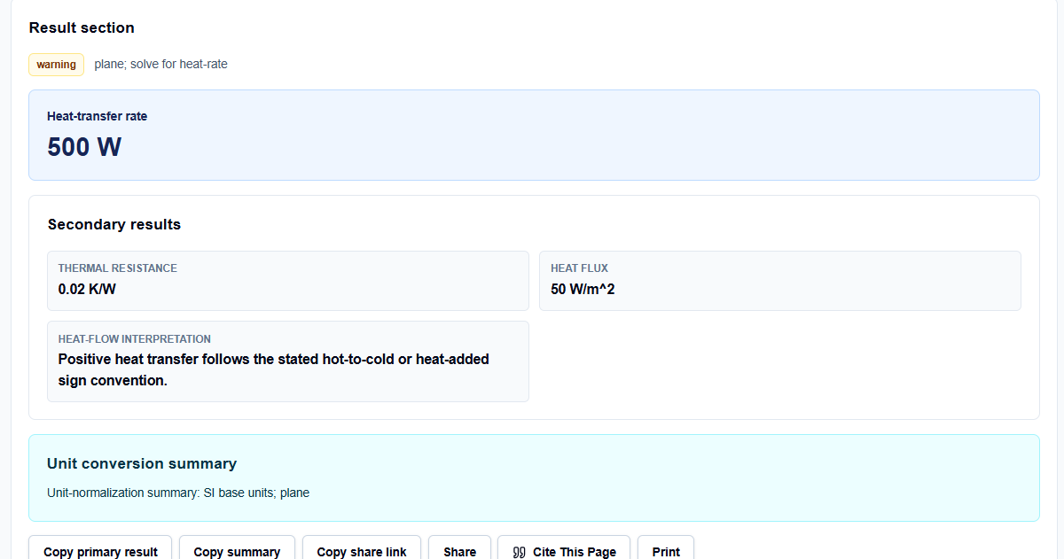
- Primary Heat-Transfer Rate (Q): Calculates the steady 1D heat flow in Watts based on the selected resistance form.
- Thermal Resistance (Rcond): Reports the conduction resistance in K/W, illustrating the thermal barrier’s strength.
- Heat Flux (q): Standardizes the heat flow per unit normal area, which is highly useful for comparing alternative insulation thicknesses.
- Engineering Interpretation: Evaluates the signed temperature change to clarify the heat-flow direction. Positive heat transfer follows the stated hot-to-cold or heat-added sign convention, while negative values indicate reversed flow.
A Practical Example: Flat Wall Sizing
Consider a realistic process engineering check. Suppose we need to calculate the steady-state heat loss through a flat insulation barrier.
We set the geometry mode to plane wall and enter:
- Thermal Conductivity (k): 0.5 W/(m K)
- Normal Area (A): 10 m2
- Signed Temperature Difference (Delta T): 20 K
- Wall Thickness (L): 0.1 m
Upon clicking calculate, the tool applies Fourier’s law: \[Q = \frac{k \cdot A \cdot \Delta T}{L}\] It calculates a primary heat-transfer rate of 1000 W. The result section helps you verify a thermal resistance of 0.02 K/W and a standardized heat flux of 100 W/m2, confirming our design limits.
Mistakes I Would Avoid
One critical mistake is using plane-wall area approximations for radial conduction. Using flat approximations on cylindrical pipes ignores log-mean area expansion, leading to severe under-insulation. Always enter inner and outer radii directly.
Another major pitfall is using diameter values where radius is required. This simple oversight doubles your geometric thickness parameters, artificially deflating heat loss estimates and risking physical system failure.
Try the Free Conduction Calculator
To eliminate manual conversion errors and protect your design data, try this tool today. It is free, secure, and runs locally.
Try the Conduction Calculator on ScholarTool Chaining this analysis with the Thermal Resistance Calculator or Overall Heat Transfer Coefficient Calculator supports related workflows. You can also determine insulation limits with the Critical Radius of Insulation Calculator or convert properties using the Thermal Conductivity Converter.
FAQ
1. Are my proprietary piping dimensions or fluid temperatures sent to ScholarTool’s servers?
No. All entered thermal conductivities, geometric parameters, and temperature bounds are parsed and calculated entirely locally on your device within your browser’s page state. No data is transmitted to an external server or third-party calculation API, ensuring complete privacy.
2. Why must I input the thermal conductivity value manually instead of selecting a material?
Thermal conductivity (\(k\)) is treated as a constant user-entered parameter because it varies significantly with temp, pressure, composition, direction, phase, and material grade. Requiring manual entries ensures you verify correct properties for your exact operating conditions.
3. Does the calculator handle Celsius and Fahrenheit temperature offsets automatically?
No. Temperature differences are treated as delta units without absolute offsets (since a temperature change of 10 Kelvin is equivalent to a change of 10 degrees Celsius, but not 10 degrees Fahrenheit). Always input your temperature differences directly as delta values.