Master Your CNC Setups with the Milling Speed Calculator
When I stand in front of a CNC controller, I often ask myself two questions: Is this feed rate aggressive enough to make real chips, or will it just rub and work-harden the material? On the flip side, am I pushing my spindle speed so high that I’ll burn the coating off a brand-new carbide end mill? Finding that “sweet spot” is the difference between a productive shift and a bin full of scrap.
That is why I rely on the Milling Speed Calculator at ScholarTool. It provides a clean, browser-local way to review your preliminary cutter setup before you commit to a CAM toolpath or manual move. Whether you need to find the right RPM for a specific surface speed or reverse-check a programmed feed rate to see the actual chip load, this tool gets you the numbers without the clutter.
What the Milling Speed Calculator Helps You Do
The primary purpose of this tool is to harmonize the relationship between your tool geometry, spindle velocity, and table feed. I find it particularly useful during the planning phase for slotting, profiling, and facing operations.
What I appreciate most is the focus on privacy. When you enter your proprietary manufacturing dimensions or material assumptions, the calculator processes everything locally in your browser. You don’t have to worry about uploading CAD files or drawings to an external API just to get a basic RPM check. It is a deterministic, fast utility designed for the shop floor where speed and security matter.
Inputs You Can Use
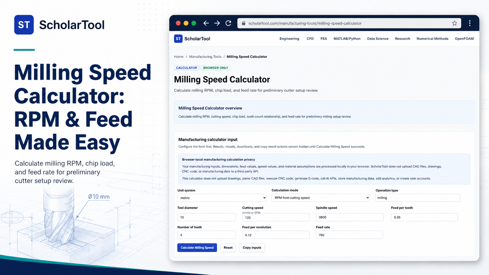
The interface is structured to let you configure your setup first. You can choose between Metric (millimeters, meters per minute) and Inch (inches, surface feet per minute) unit systems.
I see four calculation modes that cover nearly every common shop scenario:
- RPM from Cutting Speed: Use this when you have a manufacturer’s recommended SFM or $v_c$ and need to set your spindle.
- Cutting Speed from RPM: Perfect for checking if your current spindle speed is over-cooking the tool.
- Feed Rate from Chip Load: This is my go-to for ensuring I’m meeting the target “bite” per tooth.
- Chip Load from Feed Rate: I use this for reverse-checking CAM outputs or manual settings.
Specific fields include the tool diameter ($D$), cutting speed ($v_c$), spindle speed ($n$), feed per tooth ($f_z$), and number of teeth ($z$). You can even see the feed per revolution ($f_n$) and the final feed rate ($V_f$).
How I Use the Tool
When I open the interface, my first step is selecting the Unit System. If I’m working with a metric drawing, I stick to millimeters. I then select the Calculation Mode.
For a new end mill, I’ll look up the tool supplier’s chip load and surface speed. I enter the tool diameter and the number of teeth—don’t forget the tooth count, as it’s a common source of error! Once I’ve typed in my speeds and feeds, I click the Calculate Milling Speed button.
I’ve noticed that results, visuals, and download options remain hidden until you click that button. This is a smart design choice; it prevents you from accidentally using pre-filled or stale data that doesn’t reflect your current setup.
Understanding the Results
The primary results include your calculated Spindle Speed ($n$) and Feed Rate ($V_f$). What I find helpful here is that the tool also provides the underlying formulas, such as $V_f = f_z \times z \times n$, so you can verify the logic for yourself.
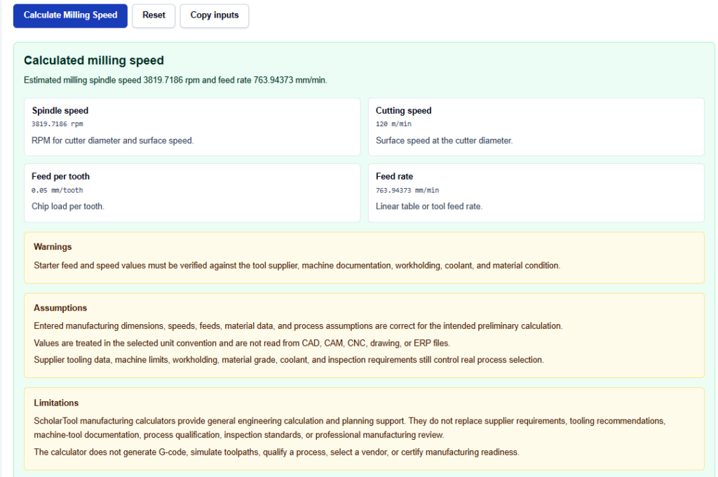
The output interpretation section reminds you that a chip load that is too low may cause rubbing, while one that is too high can overload your tool or machine. If the result looks off, I usually use the “Copy inputs” button to save my data before trying a different mode.
A Practical Example
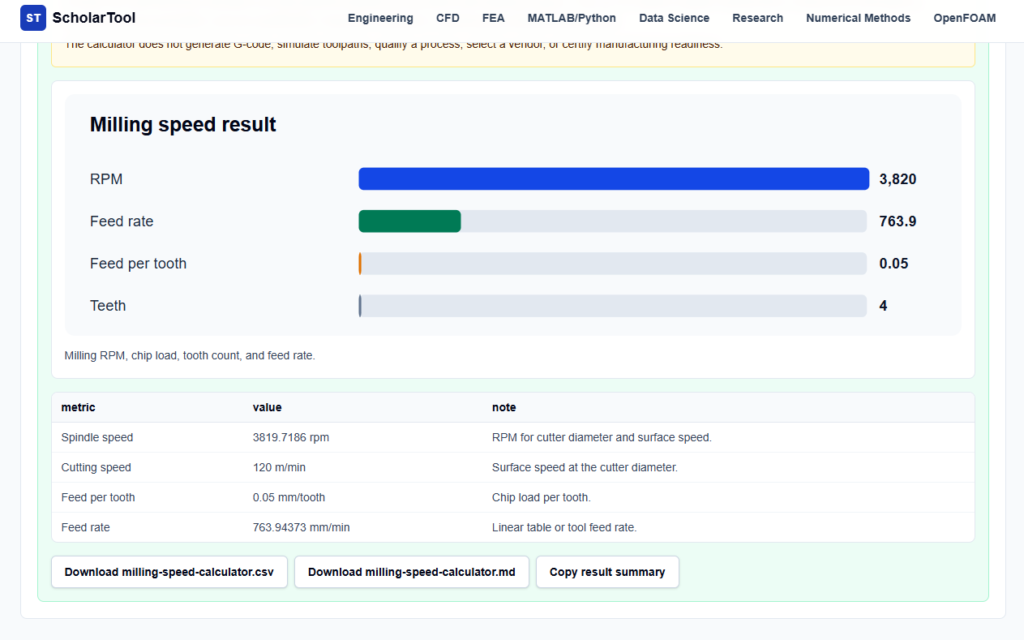
If I’m using a 10 mm 4-flute cutter and my material data suggests a cutting speed of 120 m/min with a chip load of 0.05 mm/tooth, I select the “RPM from cutting speed” and “Feed rate from chip load” modes.
When I run the calculation, I see an RPM of approximately 3,820 and a feed rate of roughly 764 mm/min. I then compare this to my machine’s maximum spindle speed. If my machine only hits 3,000 RPM, I would switch to the “Cutting speed from RPM” mode to see how that affects my surface speed and then recalculate my feed.
Mistakes I Would Avoid
One major pitfall I see is ignoring Radial Chip Thinning. Note that this calculator assumes 100% engagement (slotting). If you are taking a very light peripheral cut less than half the cutter diameter your actual chip will be thinner than the programmed $f_z$. You may need to manually increase your feed rate to compensate and prevent the tool from rubbing.
Another mistake is forgetting that this tool provides a preliminary review. It does not account for tool deflection or the power curves of your specific spindle. Always verify the result against your machine’s documentation and the rigidity of your workholding.
Try the Free Milling Speed Calculator
Before your next cut, take a minute to verify your parameters. It’s safer for your tools and better for your finish.
Try the Milling Speed Calculator here.
For a more comprehensive analysis, you can also explore the CNC Feed and Speed Calculator or use the Material Removal Rate Calculator to check your machine’s load limits.
FAQ Section
1. Does this calculator save my manufacturing data?
No. All inputs and calculations are performed browser-locally. ScholarTool does not upload your dimensions or assumptions to any third-party APIs or databases.
2. Why can’t I see the results immediately after typing?
ScholarTool requires an explicit click on the “Calculate Milling Speed” button. This ensures you have reviewed your inputs—like tooth count and units—before using the output in a real-world setup.
3. Does the tool adjust for very shallow radial cuts?
The tool does not currently correct for radial chip thinning. If your width of cut is less than 50% of the diameter, you may need to adjust your feed rate upward based on external chip thinning formulas.