
Reynolds Number Calculator: Pipe & External CFD Tool
When I am setting up a Computational Fluid Dynamics (CFD) simulation or designing a piping network, the most critical decision I face is determining the flow regime. Is the fluid moving in smooth, predictable layers, or is it characterized by the chaotic eddies of turbulence? Choosing the wrong solver ,applying a laminar model to a high-speed turbulent flow, for example,will lead to non-physical results and failed convergence. To bridge this gap between raw parameters and simulation logic, I rely on the ScholarTool Reynolds Number Calculator.
This calculator is a deterministic, browser-local utility designed to compare inertial and viscous effects through the dimensionless Reynolds number ($Re$). Whether you are defining boundary conditions for an OpenFOAM run or auditing experimental data, this tool ensures your dimensionless context is mathematically sound without ever submitting your proprietary specs to a third-party API.
What the Reynolds Number Calculator Helps You Do
The primary purpose of this tool is to identify the state of fluid motion for internal or external flows. In technical terms, $Re$ is the ratio of inertial forces to viscous forces. As the ScholarTool interface demonstrates, this single number dictates whether a flow is laminar, transitional, or turbulent.
I find this specifically useful when working with non-circular geometries. While a circular pipe transition is well-documented, resolving the regime for a concentric annulus or a rectangular duct requires more than just a quick guess. The tool automates these complex derivations, providing the “Engineering interpretation” necessary to decide if your Reynolds number falls within the commonly cited turbulent range (e.g., above 4000 for internal flow).
A Comparative Perspective: Geometry vs. Dynamics
From a comparative perspective, it is useful to see how this tool relates to the Hydraulic Diameter Calculator. While the Hydraulic Diameter Calculator is dedicated strictly to resolving the geometric scale ($D_h$) of a flow passage, the Reynolds Number Calculator represents the integration of that scale with fluid properties and velocity.
In my workflow, I often use these in tandem. You might use the Hydraulic Diameter Calculator logic to understand the effective length of a custom duct, but the Reynolds Number Calculator is what turns that geometry into a dynamic parameter ($Re = V L / \nu$). Using this tool ensures that your “characteristic length” is correctly paired with the fluid’s mass density and viscosity, preventing the common mistake of applying internal flow thresholds to external boundary layers.
Inputs You Can Use
The interface provides a logical, modular layout that allows you to configure your simulation parameters before committing to a solver setup.
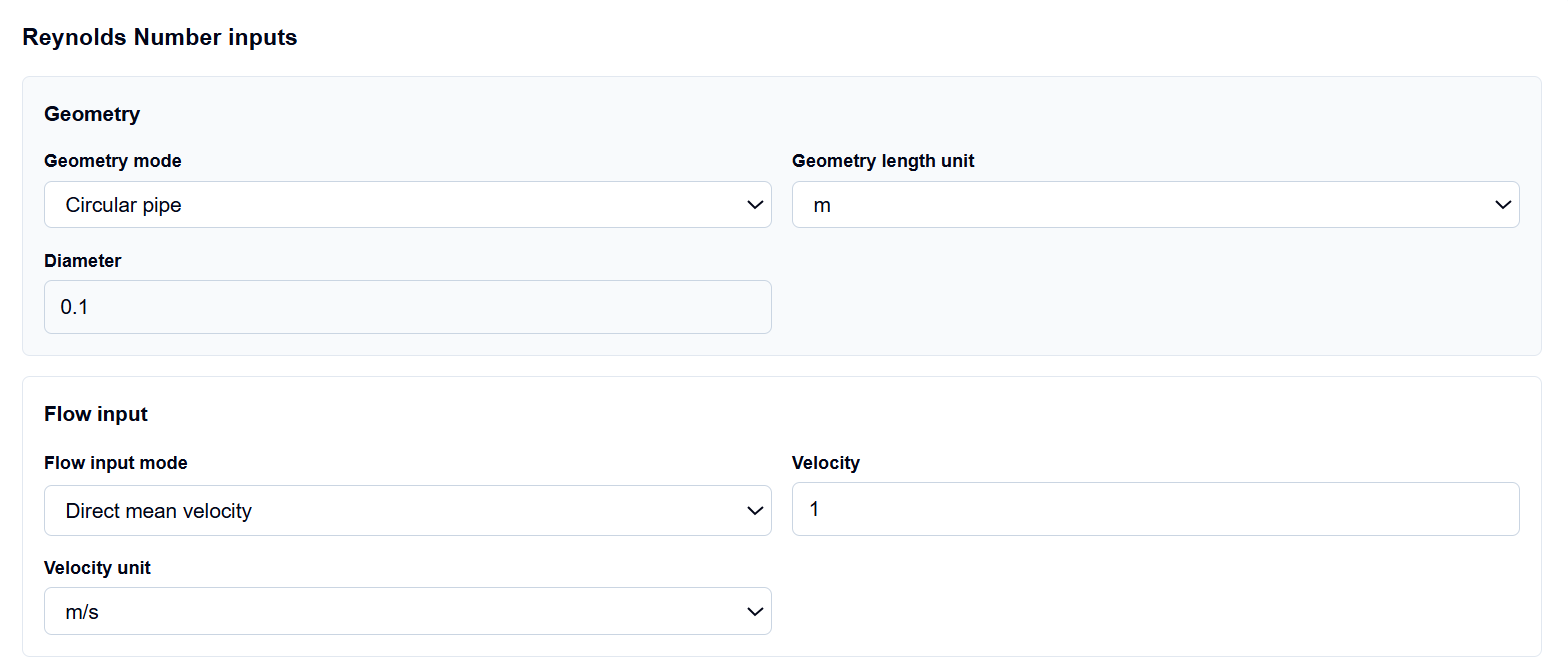
Geometry and Characteristic Length
You can choose from several Geometry modes, including circular pipes, rectangular/square ducts, and concentric annuli. What I find particularly professional is the “External/general characteristic length” mode, which allows me to specify a chord length for an airfoil or a plate length for boundary layer analysis.
Flow and Fluid Logic
The tool supports three Flow input modes:
- Direct mean velocity: Standard entry in m/s, km/h, ft/s, or mph.
- Volumetric flow rate and area: Useful when you only have the GPM or $m^3/s$ data.
- Mass flow rate, density, and area: Essential for compressible gas workflows.
For fluid properties, you can use Fluid presets (like Water or Air at 20 °C) or enter Manual properties. I’ve observed that the tool allows you to toggle between Dynamic and Kinematic viscosity; if you use Dynamic mode, you must provide density to resolve the formula $Re = \rho V L / \mu$.
How I Use the Tool
My typical workflow starts with the fluid preset. If I am simulating water at ambient conditions, I select the preset to quickly pull the 1,000 kg/m³ density and 0.001 Pa·s viscosity into the calculator.
Next, I configure the geometry. If I’m designing a cooling sleeve, I select “Concentric annulus” and enter the inner and outer diameters. I appreciate that the tool is “browser-only,” meaning the TypeScript logic executes locally on my machine. Once the calculation is triggered, I review the Calculation steps to see exactly how the tool resolved the geometry and velocity before arriving at the final $Re$.
Understanding the Results
The result section provides the Reynolds number prominently. However, for professional documentation, I find the Secondary results and Unit-normalization summary indispensable. The tool explicitly shows the derived velocity and the calculated hydraulic diameter it used.

The tool provides a step-by-step breakdown of the math and a professional interpretation of the resulting regime.
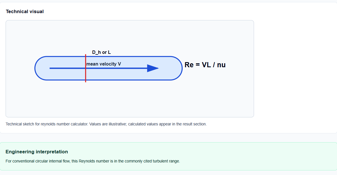
If I am moving this data into a friction factor calculation, I use the Copy primary result button to maintain high precision. I also find the Technical visual helpful; it provides a sketch of the flow and geometry relationships, serving as a sanity check that I’ve applied the mean velocity and characteristic length to the correct physical feature.
A Practical Example
Suppose I am verifying the flow of water ($1,000\text{ kg/m}^3$) through a 0.1 m diameter pipe at a velocity of 1 m/s. I enter these values and select Dynamic viscosity (0.001 Pa·s).
The calculator resolves this as Re = 100,000. The Engineering interpretation instantly notes that for conventional circular internal flow, this value is in the turbulent range. This result allows me to confidently proceed with a $k$-$\epsilon$ or $k$-$\omega$ SST turbulence model in my CFD solver rather than attempting a laminar setup.
Mistakes I Would Avoid
One common pitfall is applying circular-pipe thresholds to external flow. If you calculate a Reynolds number of 3,000 for a wing chord, it is not “turbulent” in the same way a pipe flow would be; the transition physics are entirely different.
Another mistake is using dynamic viscosity without density. The formula $Re = \rho V L / \mu$ depends on mass density to cancel out the mass units in the viscosity term. I always double-check the “Kinematic viscosity” secondary result to ensure the fluid properties match my intended operating temperature and pressure.
Try the Free Reynolds Number Calculator
Before you hit “Initialize” on your next CFD run, take a moment to verify your flow regime. It is the fastest way to ground your boundary conditions in physical reality.
Try the Reynolds Number Calculator here.
To complete your simulation setup, you may also find the Friction Factor Calculator, Turbulence Intensity Calculator, or the Y Plus Calculator essential for your workflow.
FAQ
1. What Reynolds number is considered turbulent for a circular pipe?
For conventional internal flow in circular pipes, a Reynolds number above approximately 4,000 is commonly treated as turbulent. This is explicitly noted in the tool’s engineering interpretation section.
2. Can the Reynolds number be negative?
No. The calculator uses velocity magnitude because the Reynolds number is a dimensionless magnitude representing the relationship between inertial and viscous forces.
3. Does this tool help me choose a turbulence model?
The calculator identifies the flow regime (laminar vs. turbulent), but it does not select a specific turbulence model (like $k$-$\epsilon$) for you. You must use the $Re$ result and your own professional judgment based on the simulation requirements.